Geometry
The graphical user interface offers very good possibilities to the users to model geometries quickly and uncomplicatedly. This is a special essential for contours, which cannot be described by lines and circular arcs. The effects of changed geometric data are immediately shown in corespondending graphical windows. The node chains are created in such a way, that with regard to the actualk designed motor geometry a good mesh quality as base for the accurate FEM calulations is created. Additional can user adapt the node densities individually on every node chain.
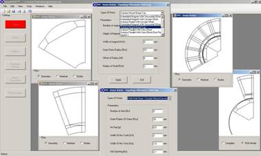
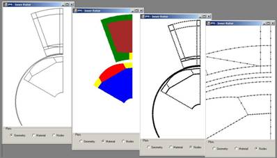
smartFEM offers different possibilities to illustrate the design of geometry, material and node chains. Viewing details in all illustrations is supported by an extended zoom function.
For minimizing the numbers of mesh nodes and with that the calculation time smartFEM and FEMAG uses symmetries in the motor design whereby all calculation results are presented for the complete maschine. The calculations are carried out linear oder non linear related to specified material data.
smartFEM provides different pre-prepeared Topologies as base for further design of the geometries including IEC standards for stamped iron plates. Also available is a Toplogy Maker with which users can define their own topologies and test/debug them in direct interactions with smartFEM.
Rotor- and Stator Geometries (selection)
The simulation models incl. all related calculation results are saved as text and pictures in one XML formatted file. With this have user access to all data via other applications. Additionally a simple project and version management is possible.